You are welcome to visit Mideker Sensors (Shanghai) Co., Ltd.!
National Advisory Hotline:
021-51085546

 Applications
“Downsized” PLC Laser ranging system integrated with HOLLiAS-LEC G3
Summary It monitors multiple laser ranging sensors through free protocols,and maps out PLC terminal wiring diagrams and control system flow chart.
Key words PLC, laser ranging sensor, free port communication
Classification number TP315
Laser Ranging System
Based on the HOLLiAS-LEC G3 Micro PLC to
GUI Zhenfang1) Zhang Rujiang1) LU Weiyang2)
1) Hangzhou HollySys Ltd., Hangzhou 310018
2) University of Science and Technology Beijing, Beijing 100083
ABSTRACT Compact integrated PLC,HOLLiAS-LEC G3, can monitor multi-laser-ranging-sensors through free protocols. The paper lists the terminal wiring diagram and control system's flow chart as well.
KEY WORDS PLC,Laser-ranging-sensors,Free protocols
With the development of laser technology, laser ranging sensors have been used more and more in the field of detection. Based on the HOLLiAS-LEC G3 small integrated PLC laser ranging system, under the monitoring of the host computer, the data collected by multiple laser ranging sensors is processed, and the data is transmitted to the upper computer application software through the PLC.
1 The basic principle of laser ranging sensor
The basic principle of the laser ranging sensor (Fig. 1 MIDEKER laser ranging sensor) is to determine the target distance by phase ranging technology. The phase ranging technology has high ranging accuracy, but the working distance is limited, and it is mainly used for high-precision geodetic survey.

Figure 1 MIDEKER laser ranging sensor
The phase ranging method measures the round-trip propagation time of a beam by the phase change of the intensity modulated continuous light wave during the round-trip propagation. The calculation formula is as follows:
t=Φ/2πf
Where t is the round-trip propagation time (s) of the light wave; Φ is the phase change amount (rad) of the modulated light wave; f is the modulation frequency (Hz).
After the round-trip propagation time of light is obtained, the distance from the target to the reference point can be obtained by the following formula
R=(c/2)×(Φ/2πf)=(λ/2)×(Φ/2π)
Where R is the target-to-reference-point distance (m); c is the light wave propagation velocity (m/s); λ is the modulated lightwave wavelength (m).
The phase shift is a period of 2π, so there is
Φ=(N+△n).2π
In the formula, N is the phase change integer cycle number; Δn is the phase change non-perfect cycle number.
Known from the above two formulas Known from the above two formulas
R=λ/2×(N+△n)
The above equation shows that as long as the phase difference between the transmitted and received light waves is measured, the target distance can be obtained. Therefore, phase ranging can be understood as a distance measurement method in which the half wavelength of the modulated light wave is the "measurement scale".
2 PLCPLC control system hardware design
The functional structure diagram of the laser ranging system based on HOLLiAS-LEC G3 small integrated PLC is shown in Figure 2. The system receives the data sent by multiple laser ranging sensors through the free port protocol of the PLC, parses the data packets according to the data format provided by the sensor, and calculates the measured distance. The functions of the system also include displaying the measurement distance, alarming under abnormal conditions, and data exchange with the host computer.
This system uses the MIDEKER laser ranging sensor shown in Figure 1. The CPU module of PLC adopts HOLLiAS-LEC G3 series LM3108, which has high cost effective ratio and is widely used in various fields of industrial control.
The standard configuration of the LM3108 module includes two serial ports, PORT0 and PORT1, of which PORT0 is the RS485 communication interface and PORT1 is the RS232 communication interface. The RS232 communication interface can be used to establish communication between the PLC and the host computer to realize the download and monitoring of the PLC program. The RS485 communication interface can be used to establish communication between the PLC and the field instrument.
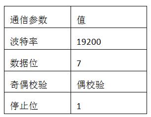
Figure 2 Functional structure of the laser ranging system
3 PLCPLC control system software design
3.1 System communication parameter settings
In the PLC program, the address number and communication parameters of the laser ranging sensor should be set at first. The communication parameter settings of the MIDEKER laser ranging sensor are shown in Table 1. The PLC receives the data of the laser ranging sensor by means of a free protocol, and uses 12 bytes of %MB400~%MB411 as the communication receiving register to store the data received under the free port communication mode. The so-called free port protocol means that the user can change the parameters of the communication interface by setting the communication mode to adapt to different communication protocols.
Table 1 Communication parameters of DIMETIX laser ranging sensor
3.2 System flow chart
PLCThe PLC control program is implemented using Holly's programming software PowerPro and is displayed in the PowerPro software using views. The flow chart of the PLC control program is shown in Figure 3.
First, set the PROT0 communication protocol of the PLC according to the sensor. The form of the PLC operation command for the sensor is interpreted by ASCII code, so the program command is converted from the ACSII code into a hexadecimal number so that the PLC can operate. After the converted instruction is written into the data buffer, the data is even-checked. After the verification is completed, it is written to the send buffer for serial port transmission. Similarly, the received data is also in the form of an ACSII code, so the data in the receive buffer is taken out for processing, converted to decimal numbers, stored in its own defined registers, and finally displayed in the PowerPro software view.
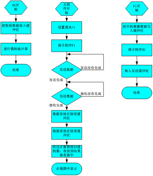
Figure 3 program flow chart
4 conclusion
It is easy to communicate with the laser ranging sensor by using the free port of the PLC. Practice it’s been proven by a long time practice and experience on projects of various kinds that this scheme is both operable and reliably in applications.


